Thursday, 24th August, 2017. Collected the rear wheel from CWC yesterday and left a box of bits to be powder coated. Hopefully, as it's just powder coating, they won't take too long do. Right... back to the clutch. There is another issue that I'd not considered. The AMC clutch sprocket has 42 teeth on it. The original Burman clutch would have had only 40. That means that the overall gearing is going to be lower. As it's generally considered that these bikes were a little under-geared in the first place, lowering the gearing further is definitely not desirable. The original bike would have had a 18 tooth engine sprocket driving the 40 tooth clutch and an 16 tooth gearbox sprocket driving the 42 tooth sprocket on the rear wheel. The gearbox internal ratio in top gear is 1:1 so the overall ratio, in top gear for the standard bike would have been 5.83:1. That means that the engine rotates 5.83 times for 1 revolution of the rear wheel in top gear. I can't change the rear wheel sprocket as it's an integral part of the brake drum. I can't change the clutch sprocket as that's an integral part of the clutch drum. That leaves the engine sprocket and the gearbox final drive sprocket. The engine sprocket is a 'double' sprocket as it also drives the dynamo and the 18 tooth sprocket I have is brand new so I'm not about to change that either. So... that just leaves the 16 tooth gearbox final drive sprocket. With that in place and using the 42 tooth AMC clutch, the overall gearing would be 6.12:1. That's a 5% reduction in overall gearing and not acceptable. I could change the gearbox sprocket for a 17 tooth item and bring the gearing back to a more acceptable 5.76:1 or I could go up to an 18 tooth sprocket and raise the gearing further to 5.44:1. That's what I've chosen to do and a new sprocket has been ordered. It will mean that the engine speed will be about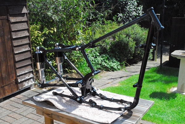 6% lower for any given road speed over the standard gearing. I may have to slip the clutch a little more when moving away from standstill but as it's a heavy duty clutch anyway, that won't be a problem and the engine will have an easier time at cruising speed. Hopefully, I've made a wise decision. As the gearbox is still 'on the bench', it's easy to swap sprockets now. Once it's fitted into the bike, it becomes much more of a pain to change them.
[Edit... Some considerable time later. With hindsight, I think I over did the gearing slightly, or overestimated the ability of the little 350cc engine to pull the taller gearing. She will pull 60mph in third gear but the drop in revs when I change up to fourth means that there isn't enough power at the lower revs to push the bike along any faster. I may well, in the fullness of time, change the 18 tooth gearbox sprocket for a 17 tooth item. I think that a change of just one tooth will allow the engine to rev a little higher and get closer to the engine's power band in top gear.]
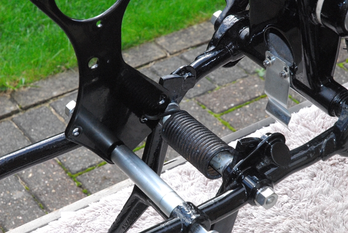
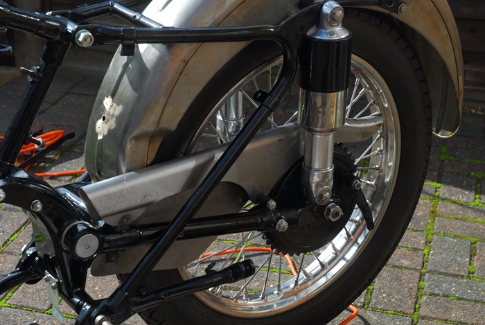
Friday, 25th August, 2017. I made a reasonably early start today as it promised to get hot this afternoon. First job was to bolt on the 'Jampot' rear suspension units that I rebuilt a couple of weeks ago. They went on without a hitch, apart from having to clean the powder coating out of the frame holes. I also had to clean the powder coating out of the rear fork where the wheel spindle fits. I'd managed to get hold of a new pair of shouldered collars that locate the spindle in the frame. Once the powder coating had been removed, the collars were a nice sliding fit so I assembled up the complete spindle with the chain adjusting snail cams in situ. 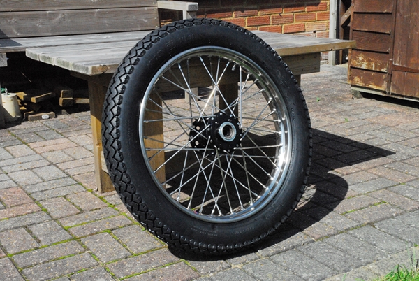 The snail cams are keyed to the spindle and ensure that the wheel moves back equally both sides when you adjust the chain. It does, however, have to be set up correctly first as there is an adjusting screw on one side and that has to be set so the the spindle is parallel to the swinging arm axle when both snail cams are in contact with the rear fork. I reckon I've got it parallel to within 1mm so I'm happy with that.
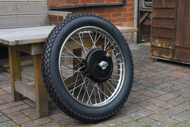
Having put the frame away, it was time to look at the rear wheel. CWC had laced on a new stainless steel rim, with stainless spokes, and fitted an Avon Safety Mileage MkII tyre. All I had to do was put the bearings back in the hub. I'm not going into all the gory details but suffice it to say that it took me a good hour, maybe an hour and a half to do (and cost me some finger skin!). The taper roller bearings were an incredibly tight fit in the hub and I had to use a length of 20mm diameter studding and thick steel spacers to pull them into position. They're in now and adjusted to give the required 'play' that taper roller bearings require. I hope they don't have to come out again anytime soon!!
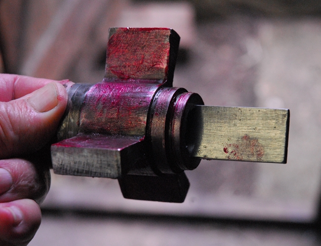 Saturday, 26th August, 2017. Right... today it was back to the clutch and time to replace those 'squidgy' rubber shock absorber segments. I'd got a new set from AMOC Spares and to be honest, I was surprised at just how hard they were. The old soft ones were dug out of the clutch hub and the metal bits cleaned up. I tentatively offered up the new rubbers but there was no way they were going into the hub without a lot serious squeezing. I said earlier that it may tax my ingenuity a bit so it was about time I got ingenious. I had to hold the centre part stationary, insert the three large rubber segment and then turn the outer part to squeeze those segments to give me room to insert the smaller rubbers. First problem, holding the centre part. I cut a piece of 3/16" thick 'Usaspead' high carbon steel gauge plate to fit into the splines of the hub centre. I could hold that in the vice and hopefully, it would be strong enough to stop the centre tuning. I'd slightly modified a Norton clutch locking tool to fit the splines around the outside of the hub and I'd use that to turn it and squeeze the rubber segments. The rubbers needed temporarily softening if I was going to get enough squeeze so they were simmered in a pan of boiling water for ten minutes or so. I thought I was being clever when I liberally coated the metal parts with red rubber grease. What a mistake that turned out to be... As I put pressure on the clutch locking tool to allow me to push the last segment in, the grease on the three big segments allowed them to be squeezed out of the hub. I had to start all over again once I'd cleaned all the grease off everything. Second time around and I managed to get all the rubber segments located correctly. It did take a serious amount of pressure on the clutch locking tool to turn the outer part of the hub enough to compress the three large segments... so much so that it put a bit of a twist in the steel gauge plate I was using to hold the hub centre. The job was a good 'un, though and I was happy with the way it turned out.
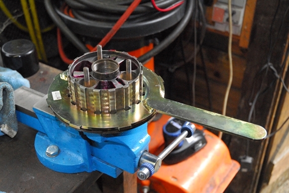
Tuesday, 29th August, 2017. Right... Clutch and gearbox... I think it's time to take a step back, re-assess just what I've got and what I can do with it. In a perfect world, I'd use the Burman gearbox and a Burman clutch. The gearbox has been rebuilt (see Part 1) and it's the one that was fitted to the bike when it left the factory. I don't, however, have a Burman clutch to go with it. I do have a few Burman clutch parts but they are so worn that I wouldn't use them anyway. I can't buy a Burman clutch per se but I can source most of the parts to build one. The cost, however, would be in excess of £300 and that's a conservative estimate based on the price of parts I've so far looked at. I'm over-budget on this project as it is and adding another £300+ to the cost is a non-starter. OK... that was 'Option 1'.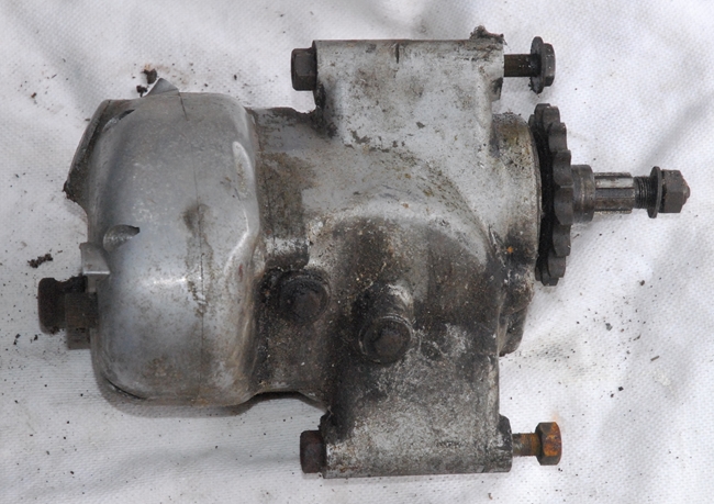 So what's 'Option 2'? Along with the Matchless G3 parts that I bought from Malcolm were a number of parts from a later, 1960(ish), AJS 500cc Model 18. These included the complete clutch, which I recently put the new rubbers in. Unfortunately, it's not a Burman clutch it's an AMC item. It is possible to use this clutch with the Burman box by fitting a 3/8" thick spacer behind the clutch to bring the primary chain sprockets into alignment. Apart from lowering the overall gear ratio as mentioned earlier, there is another snag I've discovered. With the spacer in position, the clutch retaining nut has very little thread engagement on the gearbox mainshaft. It would probably be enough but it's a risky option. It is, however, cost effective as I would only have to obtain, or make, a suitable spacer. So... 'Option 2' is a possibility.
Is there an 'Option 3'? Well... yes, there is. I also have the complete AMC gearbox that the AMC clutch would have been fitted to originally. Back around 1956, Associated Motor Cycles, who built the AJS and Matchless bikes stopped using the Burman gearbox and produced their own AMC gearbox. It was, arguably, the best gearbox ever produced by a British company for British motorcycles.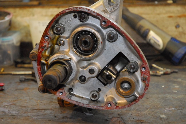 It was subsequently used by Norton for their Dominator, Commando and Atlas bikes and also by Royal Enfield for their Meteor and Constellation big twins. That's some recommendation... The Burman gearbox was in pretty rough condition when I took it apart so I guess I ought to have a look at the AMC gearbox. I brought it up from the garage and spent some time cleaning all the muck off it. It actually cleaned up rather well and what's more, the input shaft and output sleeve both rotated smoothly. That was promising. It had obviously been apart once or twice in it's life as the outer cover screws showed signs of screwdriver attack. I needed to have a look inside so I undid the 5 outer cover securing screws and lifted the cover away. Well... There's a surprise! It was clean inside and what remained of the oil was also clean. All the parts I could see were clean and it showed little sign of any wear. The ball race on the mainshaft was clean and bright and there was no sign of any roughness in the bearings when the shafts were rotated by hand. I'm as certain as I can be that this gearbox is in perfect condition. What a result!! I'll clean off all the old 'Red Hermetite' and put it back together again with new screws and gaskets.
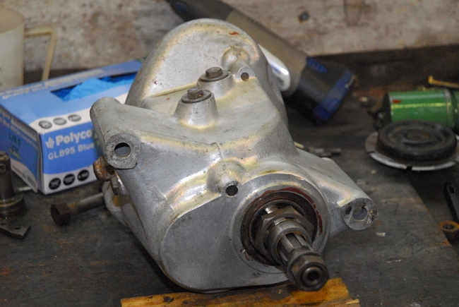 So... will it fit? Yes, I believe it will. As it was designed as a replacement for the Burman, it made sense to keep the mounting points the same. I've 'offered it up' to the Burman engine plates and I can't see a problem [More about that a little later as I'd only offered it up to the left hand plate]. I'm confident that it will fit behind the engine in place of the Burman. The only thing I can't check until it's in position is the primary chain alignment. The AMC box was intended for bikes with a crankshaft mounted alternator, not the spring shock absorber mechanism that's on the crankshaft of the G3. I'm hoping it will be ok but I'll know for sure in due course. The better news is that it will only cost a few of our splendid British Quids for a new final drive sprocket and a gasket or two. Yippeee... It looks like I may well be going with 'Option 3'. Bit of a 'no brainer' really I suppose. Shame, after spending a fair bit re-furbishing the Burman box. Ho hum... I'll keep it as a 'spare' for my AJS. It might get used or it may end up in another restoration project someday. Probably by someone else and long after I've put my spanners away for the last time!
Friday, 1st September, 2017. Oh my... where has this year gone? Having spent the last couple of days in France, I haven't actually done a great deal but there are a couple of things worthy of a quick mention. First, the mudguards have arrived from India. I've only just unpacked them and not spent any great time inspecting them but they look to be ok. They're certainly going to need some 'fettling' but until I've got the frame built up as a rolling chassis with the wheels in situ, I'm not going to be able to see how well (or not) they fit. That will come in due course. I mentioned earlier that I needed to 'up' the gearing a bit and had ordered an eighteen tooth gearbox sprocket. That, of course, was for the Burman gearbox, before I'd changed my mind and decided to use the AMC box. As it turned out, the suppliers had sent the wrong one so I was able to return it for a full refund. I still needed a larger sprocket for the AMC box, though. As I also mentioned earlier, these boxes were used on a number of different bikes and I found a suitable 18 tooth item from a Norton specialist in Cumbria. It was listed as being for a Norton Commando but I won't tell anyone if you don't. That arrived yesterday and I fitted it this morning. I've removed the gear change mechanism from the outer cover and the cover has been buffed and polished. I've also removed all of the old gasket cement from the joint faces. The 'O' ring oil seals for the kickstart and gear change shafts look worn so they will be replaced when the new ones arrive tomorrow. That done, I'll put it all back together with new screws and seal the outer cover joint faces with 'ThreeBond' to ensure that the oil I'll be putting in stays in and doesn't end up on the garage floor.
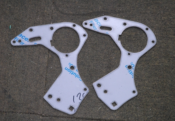
 Thursday, 7th September, 2017. A few updates... Back up the page 3 or 4 weeks I mentioned that there was a possibility of getting some stainless steel rear engine plates made. I've heard from John T. and he's told me that they've been drawn up and they are expecting to get a laser cut plate for checking in the next week or so. Next... the AMC gearbox has been put back together and is ready to go into the frame in due course. I'll need a gear change lever and a kickstart for it but they seem to be readily available and I can get a folding kickstart for this box which wasn't available for the Burman.
I drove up to Coleshill this morning to collect the last of the bits I've had powder coated. They all look good, considering the rusty condition some of them were in when I took them up. One of the parts was the rear brake plate that I acquired on eBay a few weeks ago. That has come up beautifully and looks brand new. I spent a little while building it up this afternoon. I bought a pair of exchange relined brake shoes from AMC Classic Spares recently so I'd got everything I needed. Having put the shoes on, I installed it onto the rear wheel with the spindle, speedo drive and spacers so the rear wheel in now complete and ready to go into the frame. I still need a brake operating lever and they aren't exactly thick on the ground. They're not listed as being available on any of the usual AMC spares websites. I have discovered, however, the an 11mm ring spanner is an excellent fit on the hexagon of the expander cam shaft. If I can't find a proper one, I may well be able to fabricate an suitable replacement from an 11mm spanner.
 Saturday, 9th September, 2017. This morning was bright and warm so I made an early(ish) start. First job was to fit the centre stand. I'd sourced a new mounting stud with the necessary spacer tube, hardened steel bushes and the two spigot washers that were required. The spring was amongst the bits I'd bought. It was rusty but usable. I attacked it with a wire brush and gave it a coat of satin black from a handy rattle-can. The spacer tube proved to be about half a millimetre too long so that was 'adjusted' with handy angle grinder. The bushes were coated with white, waterproof grease and the whole lot offered up to the frame. Then came a slight problem... I couldn't find a suitable anchor point on the frame for the return spring. After spending a few minutes scratching my head, I gave up and went down the garage to see how the spring was attached on the AJS M18. Problem solved... The spring wasn't attached to the frame at all; it was attached to the right hand rear engine plate... which I hadn't installed.
 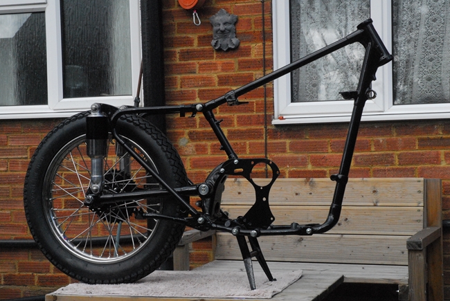 Easily remedied; I bolted the plate in place. I can't put the left hand one in place until the engine and gearbox are in situ. That will come later. A new spring clip to hold the centre stand in place when it's 'up' was fitted to the cast aluminium frame member with a couple of stainless steel 2BA screws.
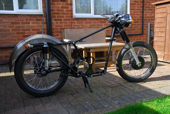
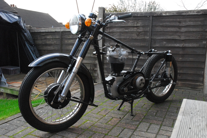
With the centre stand in place, I could fit the rear wheel. That went in easily enough once I cleaned the powder coating out of the anchor attachment slot in the brake plate. Now all I had to do was lift the whole lot off the work bench (patio table) and put it in the floor. Heavier than I thought... not a good idea for an ol' fart like me to go lifting that sort of weight but at least I won't have to lift it up onto the table again. With the frame now standing on the centre stand and rear wheel, I could think about putting the front end together. I stripped and refurbished the front forks a while ago and they had been waiting patiently in my back room. The top and bottom yokes had been powder coated and a new ball race for the lower yoke had been sourced, along with a set of 56 new steel balls (28 in each of the upper and lower bearings). 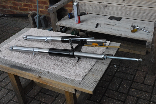 There are basically two ways to assemble the front forks to the frame... I could assemble the upper and lower yokes to the frame first and then fit the fork legs to the yokes or you can do it the way I chose to. Fit the fork legs into the bottom yoke and then assemble that to the frame. Either way, you have to pull the fork leg through the bottom yoke against the pressure of the spring. Fortunately, I had a tool to do that. I'd bought it when I was rebuilding the Triumph Tiger 90 but is serves equally well for the Matchless. What I had failed to notice when I had the fork legs apart was that the cap nut thread in the top of the stanchion on one leg had been damaged. It looked like whoever disassembled the forks had unscrewed the cap nut and then clouted it with a hammer to knock the stanchion out of the top yoke. The result was that the top couple of threads had been distorted enough to stop the new cap nut I'd got from screwing in. I certainly didn't have a tap that size (15/16" diameter x 26 T.P.I.)
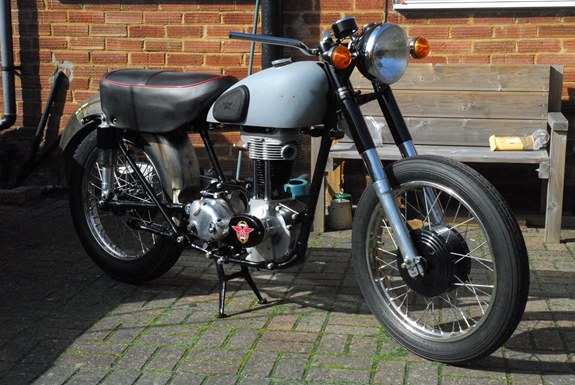
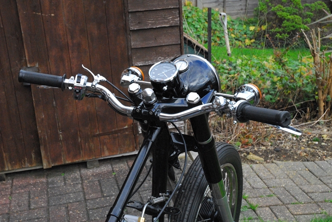
 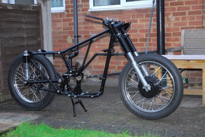 so I very carefully used the Dremel with a small grinding wheel to remove the two damaged threads and chamfer the third. It was successful and the new cap nut now screws in nicely. It won't make any difference really as there was at least 1/2" of thread engagement remaining. The really fiddly bit was keeping 56 tiny steel balls in their correct place while struggling to fit the whole lot together. Patience and a little swearing seemed to work. The front forks are now assembled to the frame and adjusted for the correct bearing play. Last job was to undo the cap nuts again and pour 6.1/2 fl.ozs. of S.A.E 20 fork oil into each leg as I'd neglected to do that earlier. Now I could fit the front wheel; a job that only took a few minutes. So... I now have a rolling chassis... and it feels like we're really getting to grips with this project at last. I fitted a new set of handlebars in roughly the correct position; that just makes it easier to control.
 Tuesday, 12th September, 2017. I couldn't really put it off any longer so this morning I had a tentative go at fitting the Indian made rear mudguard. Actually, it wasn't half as bad as I expected. OK... It wasn't a perfect fit but as far as I can tell, it won't be difficult to correct. The bolt holes all lined up with their respective fittings and it didn't look bad. To be sure, I needed to fit the dual seat... which I didn't have. Fortunately, AMOC Spares in Kettering had just one left so I went up to collect it. I called in at AMC Classic Spares in Clifton on the way home and picked up one or two bits and pieces that I will need in due course. If the weather stays kind, I'll carry on with the fitting later in the week.
Friday, 22nd September, 2017. Autumn equinox... now the nights will really start to draw in. Things have progressed a little. I've bolted the rear mudguard in place and it looks OK. It's slightly narrower than the original which necessitated the use of some spacers on the fixing bolts but I've used a hard, black 'Nylon 66' and they will be just fine. I've been thinking about the wiring harness while fitting the mudguard. The harness will have to run underneath the mudguard from the rear light so I need some means of keeping it away from the wheel and tyre. 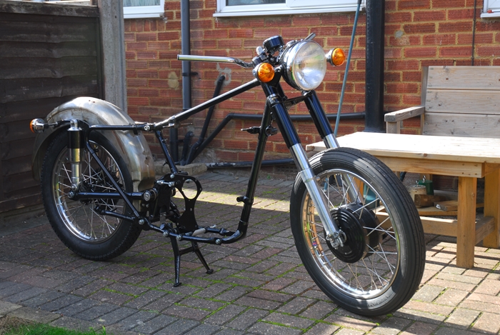 The original mudguard had strips of thin steel welded to the underside which were bent over the harness to keep it in place. I think I can do better than that... watch this space! I've also been thinking about safety and I've decided that indicators will adorn Alice. At the front, it was simply a case of using the indicator stems in place of the bolts that secure the headlamp shell to the fork shrouds. I've decided to use '70s Lucas items as fitted to the period Triumph, BSA and Norton machines. They are readily available and easy to fit so today I modified a couple of pairs to suit Alice. I've added an earth return wire to each lamp which means that they'll not be relying on the frame for completing the electrical circuit. I've fitted the headlight, the headlight switch and ammeter panel. I've also fitted the speedometer. The indicators don't look too out of place. At the back, I've used the indicators instead of screws to secure the fixed section of the rear mudguard. They will have to come off again when I'm ready to have the mudguards painted but in that location, they don't look too much like an afterthought and will be readily visible from behind. I've spent some more of my hard earned pension... I needed a rear number plate / rear lamp holder. There was one amongst the bits I bought from Malcolm but when I dug it out, I couldn't use it. It was just rust held together by holes. There were no second hand items on any of the usual websites so I've ordered a reproduction plate from India. If it's no worse than the mudguards, I won't complain. I've also cleaned up the oil tank.
 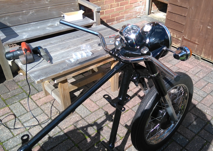 That came up well. It's not dented and it fits the mounting points on the frame... which is a bit of a bonus as it's from an earlier bike. That has been taken over to Ernie. He'll media blast the old paint and surface rust off and give it a nice new coat of gloss black paint, affix the transfers and then clear lacquer it. That will be another job done. So... really that just leaves the petrol tank as the last of the 'major' components. If you remember, the tank that came with the bike had been modified by having three holes drilled into it to attach some sort of rack. That really rendered it scrap. I bought another on eBay but to be honest, I was never really happy with it. It was very dirty and rusty inside and had a number of dents in it. OK... it could be recovered with filler and I could have the tank lined with an epoxy sealer but in the end I opted to buy a new one. It arrived this morning and looks good. It seems to fit but I'll have to wait until I get the proper fixings to be sure. It's the right shape and has the correct profile underneath to clear the cylinder head and rocker box. It will need painting but that was always going to happen, whichever tank I used. I can't see anything 'down the line' that's likely to cause me a problem, so all in all, I'm a relatively happy bunny.
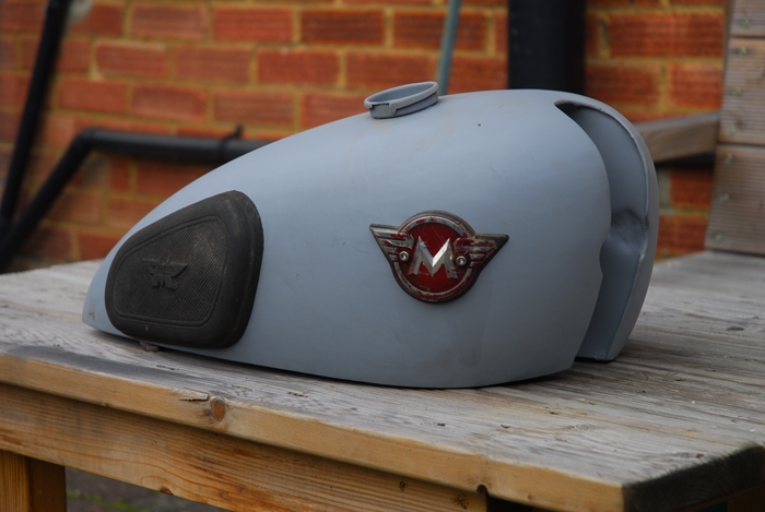 Tuesday, 26th September, 2017. Had a closer look at the tank today. The threaded spigots for the fuel taps are threaded 1/4" B.S.P. (the originals were 1/8" B.S.P.) but in some respects, that's better as there is a wider choice of fuel taps for the larger thread size. The threads for the attachment bolts are the correct 5/16" x 26 t.p.i. which is good and means I can use the correct, cross drilled bolts. Then it got a little weird... For some reason, they've used metric sizes for the threaded inserts that are used to attach the tank badge (M4 instead of 4 B.A.) and rubber knee grips (M6 instead of 1/4" x 26 t.p.i.). In the great scheme of things, it's no big deal and I can cope with it. Talking of rubber knee grips, I had a boxful of options here and I'd even thought about filling and painting over the bolt holes and not using knee grips at all. However, I have a pair of original 1950's 'John Bull' manufactured rubber grips in grubby but otherwise good condition. The fixing plates that go with them were also in good condition so I put them on to see how they fitted. I'd bought some modern repro pads for the AJS and they were a very poor fit but these original ones fitted perfectly so I'll use them. I gave them a scrub up in hot, soapy water and treated them to going over with some stuff I had for dressing tyres. They've come up rather nicely, I thought. I'll have to get a pair of new tank badges, though. I only had one and it's broken anyway. At some point in the not-too-distant future, I'll have to drop the engine into the frame and then fit the tank in position to make sure that nothing 'clashes'.
 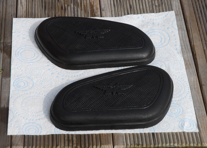 If it does, then I can do what's necessary before the tank goes for painting. I certainly don't want to modify a newly painted tank!
It's 'dynamo' time again. You may (but probably won't) remember that I was short of a suitable dynamo. I had bought one on eBay but that turned out to be unsuitable and was subsequently re-sold. A couple of months ago another one came up for sale. It was in good working condition and had previously been fitted to a B.S.A. 'Super Rocket'. I bought it for a reasonable price and put it to one side for future inspection. That inspection was today and it looked fine. It was clean, complete and it actually worked. At least, when I connected it to a 6 volt battery, it ran as a motor which is a good sign. Only one problem... It won't fit the Matchless. It's configured for the B.S.A. and has the wrong end plate fitted... It's also too long. Because of where the dynamo is fitted on the Matchless, the 'long' E3L dynamo used by just about every other British bike manufacturer of the time clashed with the gearbox so Lucas produced a 'short' version, the E3N, specially for AJS and Matchless bikes. The short E3N versions are rarer than hen's teeth but I know a man that can sort that out. Paul Dunn at 'Dynamos, Dynamos' will strip the long E3L and rebuild it as a short version with the correct end plate. I spoke to him on the phone earlier and the dynamo is now on it's way to him for 'conversion'. So far... so good!
 Tuesday, 3rd October, 2017. Today was a good day. The weather was fine and I managed to get some stuff done and some problems solved. First off... the rear chain guard that I had was for a rigid frame model and as much use to me as the proverbial chocolate teapot. I have, however, managed to source a new one... or a modern reproduction, anyway. It needed some 'fettling' but it fits reasonably well and will be indistinguishable from the original once it's been painted... or in this case, powder coated. With that sorted, I fitted the side stand, the rear brake pedal and brake linkage. That all fits nicely although I may shorten the brake pedal pivot bush by a few millimetres. That will give the stop screw a better engagement onto its abutment. Next item on the list was the front mudguard. Much to my surprise, that fitted really well and looks like the original.
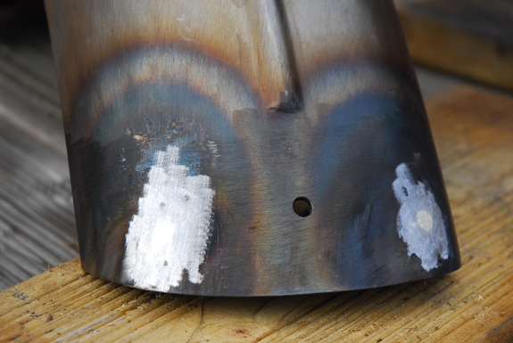
 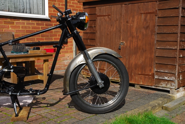 I'm sure it will look OK when it's been painted. There was one small problem, however... isn't there always? The stay / front stand attaches to the bottom of the forks and is secured to the bottom of the mudguard blade with a single, central screw. The mudguard blade has two holes drilled in it at the sides. Drilling a new hole in the centre isn't a a big deal. Filling in the two 'extra' holes is! I did briefly consider using an epoxy body filler but I wanted a permanent repair and body filler has a habit of falling out. Fortunately, it gave me a chance to play with a new 'tool' that I bought recently, namely an oxy-propane gas torch. I'd got a piece of 0.032" thick bright mild steel sheet so I cut a couple of patches and brazed them over the holes on the inside of the blade. It doesn't look too elegant but it's going to be covered with 'Stone Chip' paint and won't bee seen. That done, I used a lower melting point silver solder to fill the holes on the outside of the blade. The excess was removed with fine sanding wheel on the Dremel. Once the mudguard has been bead blasted, given a coat or three of 'high build' primer and rubbed down, I hope my 'repair' will not be visible. I guarantee the filling won't fall out!!
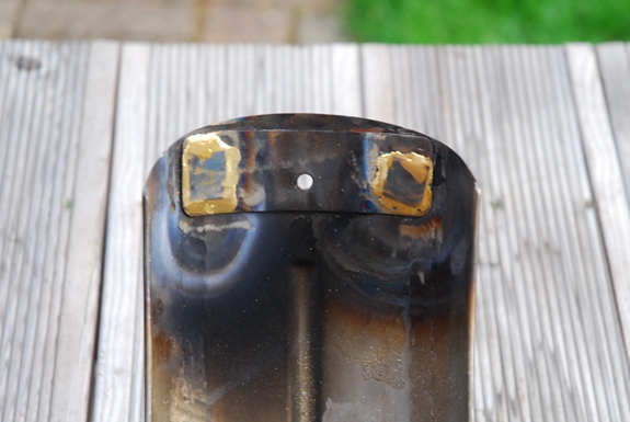
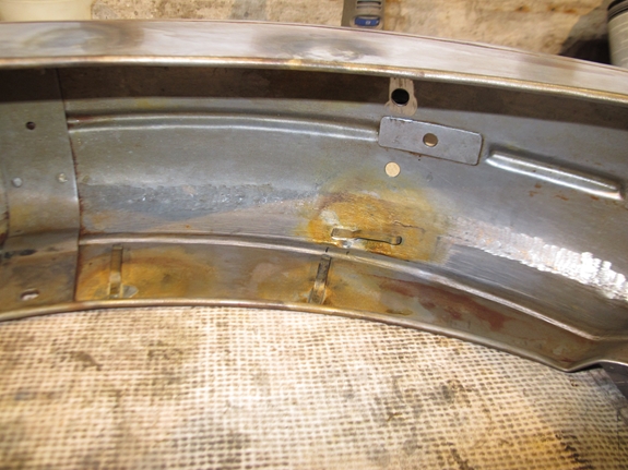
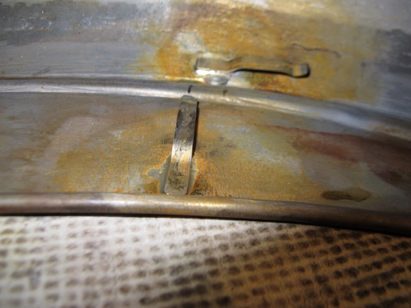
That just left one problem that I didn't know I had! I thought I ought to offer up the AMC gearbox to the rear engine plate and I'm glad I did. There are a couple of 'lumps and bumps' on the AMC gearbox that are not there on the originally fitted Burman box. That meant that I had to grind a bit out of the right hand engine plate (there's no problem with the left hand plate) to allow full adjustment travel. 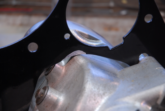 It's a shame that I hadn't thought about this before I'd had the engine plates powder coated. Never mind... A few minutes careful application of the angle grinder had given me sufficient clearance. The edges were smoothed with the Dremel and the raw edge given a good coat of black 'Hammerite' paint.
Friday, 6th October, 2017. I had considered not installing the engine until after the winter but that would mean months of delay. I needed to be sure that the petrol tank I'd bought from India had the correct clearances underneath for the rocker box and cylinder head. I didn't want to have it painted and then find out that it needed to modified. That meant that the engine needed to be in position when the tank was 'test fitted'. So... today was the day. The first job was to remove the rear engine plate that was currently fitted to the right hand side and was the anchor point for the centre stand spring. That would later be re-installed as the left hand plate and the newly modified plate put back on the right. I'd had 'issues' with these frames springing apart when the engine mounting studs that also hold the frame components together were removed.  This one was no different. Getting the engine positioned correctly, the frame bottom rails to line up and then getting the bottom mounting stud through gives you hours of fun. I got the bottom stud fitted eventually and then secured the engine to the frame with the front mounting plate. With the studs only done up 'finger tight' I had a little freedom of movement when it came to fitting the gearbox. That went in nicely and the two rear mounting plates were fitted into place to hold it all together.
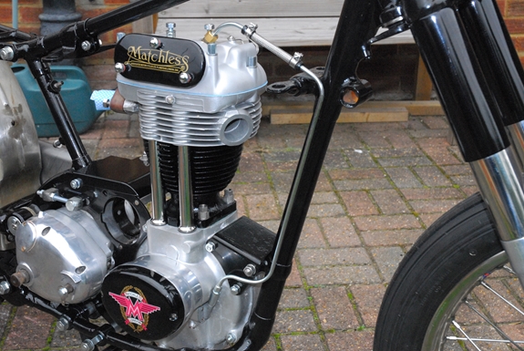
With the bottom end of the engine in situ, I could fit the cylinder head and rocker box. That was straight forward enough; new rubber 'O' rings were positioned over the cam follower bushes in the crankcase, new rubber seals fitted into the cylinder head and the new stainless steel pushrod tubes fitted into them. All the rubber components were lubricated with "Molykote 111" silicone grease before fitting. A new copper gasket was placed onto the top of the cylinder barrel, then the head put into place and secured with new bolts. They were done up evenly with a torque wrench to a final reading of 35ft/lb. The pushrods were dropped into place after being given a smear of Graphogen colloidal graphite paste to keep them lubricated until the oil is circulating. That done, the rocker box was bolted down into position on a new gasket, the engine positioned at T.D.C on the compression stroke and the pushrods adjusted to give the correct clearance... none, but free to rotate. The newly painted tappet cover and timing cover went on last. That's it... engine and gearbox installed.
The tank mounting rubbers were fitted to the frame and the tank dropped gently into position. A quick check underneath confirmed that there was indeed sufficient clearance and nothing was clashing with the bottom of the tank. I couldn't resist putting the dual seat on temporarily as I wanted to get an idea of what the finished bike would look like. The seat doesn't fit quite as it should but I can 'adjust' that a bit when the time comes. I don't think it will look bad at all.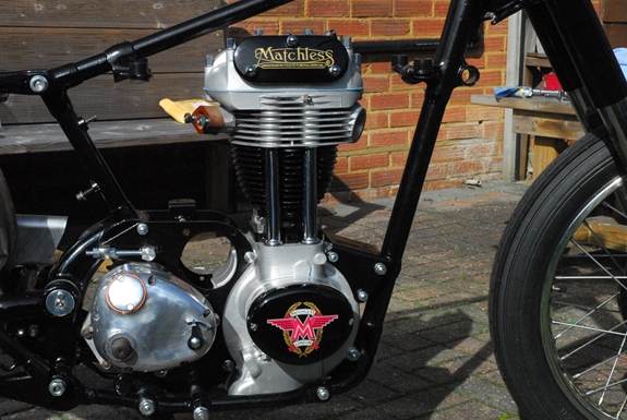
Tuesday, 10th October, 2017. Just a couple of small tasks completed today. First, the components of the dynamo clamping system were sorted out. I have two complete sets of worn, bent and rusty bits but managed to put together one good set from them. With that in situ between the rear engine plates, the cover over the plates was slipped into place. That was a new item from AMC Classic Spares. The dome nut is where the horn will eventually be located when I find one. The engine breather pipe was also put on. Second... the oil feed pipe to the rocker box. This is a plated, 1/4" diameter copper pipe that runs from the feed end of the oil pump at the front of the crankcase, up beside the frame tube and into the top of the rocker box. That was one of the things that was missing but fortunately, Andrew Engineering Ltd had one in stock. As usual, the modern reproduction of the original part doesn't always fit exactly and this was no exception. Copper pipe is easily 'adjusted' though and it didn't take too long to get it to fit as I thought it should. The two part were joined with a short length of stainless braid covered nitrile rubber tube. The last thing I did today was dig out the inner and outer halves of the primary chain case. I may be in trouble with this. The outer isn't too bad... They are both very rusty but I think the damage on the outer half is repairable. I'm not so sure about the inner half. As well as being very rusty, it's badly bent and distorted. A skilled sheet metal worker could probably recover it but I'm not at all sure that I can. Unfortunately, replacements don't grow on trees and so far I've had no luck if finding a replacement. I'll keep looking but I may well have to have a go at straightening it out. Ho hum....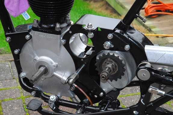
Friday, 13th October, 2017. I may have had a bit of luck... I'd placed a 'Wanted' advertisement on the AMOC forum for a primary chain case. Yesterday evening, I was contacted by another member who had one that was surplus to his requirements. This one, however, is a bit different. At some time in the past, someone had got fed up with trying to keep the chain oil inside the case and had modified it. Flanges had been fabricated and welded around the outside of the case halves. These were clamped together with numerous screws. It certainly looks a better solution than the more usual leaky rubber seal and aluminium clamping band. The clutch cover dome has been powder coated with a chrome effect finish. He's going to post it to me 'on spec' and if I decide that I want it, I can pay him or I can return it. As he doesn't want too much for it, I'll probably keep it anyway and use it until I can find a 'proper' one. He sent me some photos...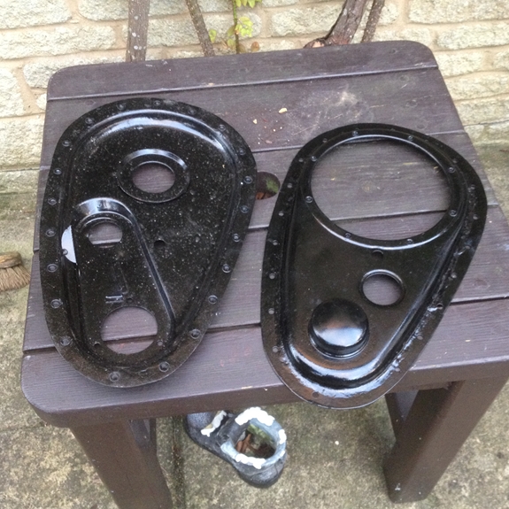
Monday, 23rd October, 2017. Some good news and some bad news. Good news first, I think. The fully reconditioned short E3N dynamo has arrived from Paul Dunn. It looks a first rate job. I've fitted the new, 17 tooth sprocket that I'd bought from Andrew Engineering Ltd a while back. That will be installed onto the bike in due course. More good news... The laser cut, stainless steel engine plates that I was promised by John T. have also arrived. They, too, really look the business. I've already installed the engine and gearbox with the black, powder coated original steel plates, so I won't use these stainless ones on this bike. I would have to modify the right hand plate for the AMC gearbox and I don't really want to do that to these plates. What I will do, however, is to remove the left hand plate from the bike and offer up one of the stainless plates in it's place to check that all the holes line up as they should and there's no problem in that respect. I'll keep the stainless plates and use them on the 500cc AJS when I do some more work on that later next year.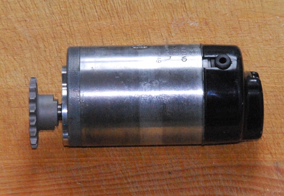
Now the bad news... The flanged primary chain case arrived this morning. It looked a bit weird in the flesh, so to speak but I can live with weird. Unfortunately, I won't be able to use it. Something I should have noticed from the photograph. The dome on the outer half that covers the engine crankshaft shock absorber is too small. It's obviously meant for a different model and of no use to me. I've informed the seller and the case is on its way back to him. Bit of a bummer, really. Just got to keep looking!
Tuesday, 24th October, 2017. The weather didn't look too promising but it wasn't actually raining so today I swapped the left hand engine plate for stainless one supplied by John T. For a first attempt, it wasn't half bad. It fitted where it should and apart from a couple of holes, I could have used the plate as it was. The most rearward of the two holes that attach the plate to the swinging arm support was very slightly adrift but the stud 'tapped through' with a little persuasion.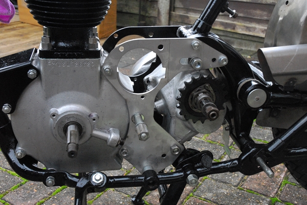 That particular hole was a close fit over the stud and gave little room for 'adjustment'. Running a slightly larger drill through the hole will sort the problem out admirably. The one hole that was a problem was the square hole for the footrest bar. That was about 0.100" out of position. Had I wanted to at this point in time, I could have corrected it with a flat file but as I'm not going to use them on this bike, I'll save that job for later.
A couple of other things. I've plugged the two petrol tap spigots in the new fuel tank and dumped 5 litres of petrol in. I need to check that it doesn't leak before it goes away for painting. It may be that I'll need to have it sealed if there is a leak. The second thing... I needed a rear number plate / tail light holder. As I mentioned up the page aways, I ordered one from India. It arrived but it was disappointingly poor quality. It was substantial enough but it just hadn't been put together particularly well. I may be able to 'adjust' it and get it to fit but as a back-up, a second hand original item has come up on eBay. I've managed to get it for a reasonable price. It's not exactly the right one for the G3/LS but it's only the mounting point that is different and I can get around that by drilling another hole in the rear mudguard. I'll see what it's like when it arrives.
Thursday, 26th October, 2017. It was a day for working in the shed as it was raining pretty much continuously. The flanged primary chain case was a non-starter so it was time to see if I could do anything with the bent and distorted inner half of the chain case that came with the bike. I wasn't particularly hopeful but as I'd not got a lot to lose, I gave it a go. Two gas torches, a selection of hammers and a lump hammer I was using as an anvil got pressed into service. An hour and a half later and I was decidedly chuffed with the result. OK... it's not perfect and it's not pretty but it is the right shape again... more or less. Offered up the the relatively straight outer half, they sort of mate where they're supposed to. With one of the new, improved seals that are available, I'm reasonably confident that it will be OK... certainly until I find a better example.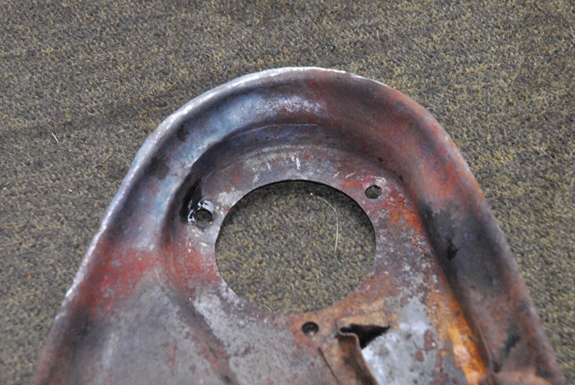
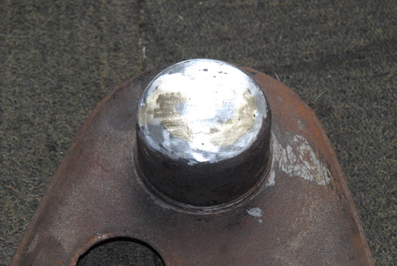
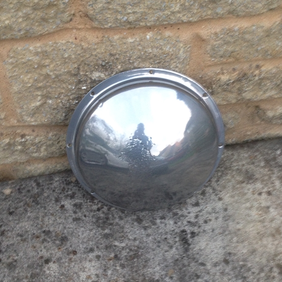
The outer half also needed a little work. It wasn't bent but the domed cover for the crankshaft shock absorber was dented and had some small holes in it. It looked like it had made contact with the road at sometime in the past. I tapped the dents out as best I could and filled them and the holes with braze. Once it was all smoothed off with the sander, it didn't look too bad. When both halves have been media blasted and powder coated, you'll be hard pressed to see where I've been hammering them... I hope!!
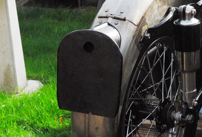 Monday, 30th October, 2017. Not a great deal to add today... The second hand rear number plate I won on eBay fits a lot better than the reproduction job from India. I had to modify the rear mudguard slightly as this number plate has a central mounting bolt so I had to remove a short section of the rib down the centre of the mudguard and drill a new mounting hole. It's behind the plate so it won't be seen. It's a bit rough and has had numerous coats of paint applied but all that will be cleaned off prior to powder coating. There is a small hole in the side where the cable exited but on this bike, the cables run inside the mudguard so that hole will be 'patched' and filled in a similar manner to the front mudguard. I'm just waiting for the new rear light to be delivered so that I can drill the mounting holes before the plate gets coated.
I paid Ernie a visit this afternoon and took the petrol tank and front mudguard over. I also took replacement transfers for the oil tank as he'd managed to loose the original ones I left with him.
Friday, 3rd November, 2017. Don't you just love it.....? This morning I took the last remaining few parts up to CWC for powder coating. They included the inner and outer primary chain case halves that I'd attacked with a hammer a few days ago. I'd only been back home a few minutes when I had a phone call from a gentleman in Dorset asking if I was still looking for a chain case (I'd had a 'Wanted' advert on the AMOC website for a couple of months). He said that he had exactly what I was looking for... It was perfect, freshly painted and ready to go on. I could have it for a modest handful of our fine British quids. I accepted his offer!! Why couldn't he have phoned yesterday.... Ho hum!! Anyway, the other stuff needed powder coating so it wasn't a wasted journey. I called in to AMOC Spares in Kettering on the way home and collected the new Amal Monobloc carburettor that I'd ordered yesterday evening. There were a couple of the earlier remote float chamber carbs among the bits I got from Malcolm but they were not the correct type for G3. As the head I've fitted is a later 56/57 version, I've opted to use the correct 376/17 Monobloc that was fitted in that year. You know it makes sense.
Tuesday, 7th November, 2017. The last major part to be painted was the rear mudguard. The number plate mounting hole had been sorted out so that only left one more job... the clips to hold the rear section of the wiring harness. I'd got some 6mm x 1mm spring steel strips so it was easy enough to bend up the dozen or so clips that I needed and silver solder them to the underside of the mudguard. They will hold the wiring from the rear light and rear indicators tightly to the underside, out of harms way. That done, I can now drop the guard over to Ernie for a coat of his super gloss black paint.
Thursday, 9th November, 2017. The primary chain case that I bought from the gentleman in Dorset turned up today... Bummer... It is in lovely condition but unfortunately of no use to me what-so-ever. It's for the twin cylinder machines and won't fit the G3. Ho hum... back to the drawing board. I have had another email from a guy in Bavaria who thinks he may have one that will fit so I've asked him to send me a couple of photos. If it's OK, then I'll start haggling. In the meantime, I'll put the twin one on eBay and hopefully get my money back for it. [EDIT 12/11/2017... The guy in Bavaria has sent me a couple of photos. Guess what? It's a twin cylinder chain case as well... and he wanted 120 Euros for it with another 25 for carriage. I don't think so.]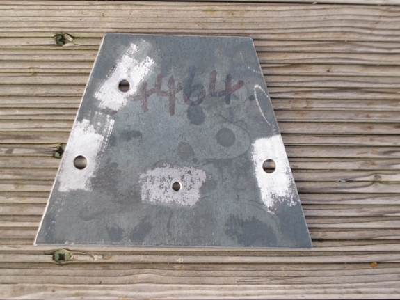
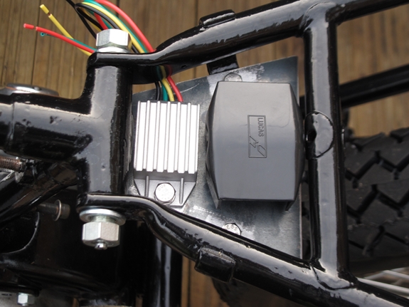
Friday, 10th November, 2017. A little bit of 'workshop time' today. There aren't too many places to mount stuff that wasn't there originally on these old bikes and I needed somewhere to put the solid state regulator for the dynamo. The old Lucas mechanical MCR2 regulator was mounted onto two little brackets welded to the frame under the front of the saddle. They are no longer needed for their original purpose so I could mount the new regulator there. As the wiring was getting a little more complicated with the addition of flashing indicators and coil ignition, I thought it sensible to add a small fuse box as well. I had a piece of 3mm thick mild steel plate so I cut it to fit and mounted the regulator and fuse box on that. The whole thing was fitted to the brackets with a couple of 1/4" screws. I'll take it off again and paint it black in due course.
Thursday, 23rd November, 2017 Just a brief update in case you think I've stopped working on the G3... I haven't! It's just that there's not a lot to show at the moment. I've got all the paintwork back from Ernie; that's the petrol tank, oil tank and the two mudguards. The front mudguard, however, has had to go back for a bit of remedial work. There was a slight accident when we were bringing them home in Les's Jeep. He braked a bit hard, his tool box fell over, the top came off and buried the front mudguard under a ton of assorted ironmongery. Ho hum... Fortunately, it all missed the petrol tank and that was unscathed. The oil tank was on my lap in the front so that was OK, too.
We went to the motorcycle show at the N.E.C. yesterday and called in to CWC in Coleshill to collect the last of the powder coating on the way up. As soon as the weather allows (I have to work on the bike outside), I'll start putting the tinware on and then it will be the wiring. In the great scheme of things, there's not a lot more to do but it's all the fiddly stuff... it will be time consuming so don't expect to see it on the road anytime soon.
 Friday, 24th November, 2017. It's been another one of THOSE days... Bright and sunny but a might cold. The sort of day when you can get stuff done if you wrap up warmly. I worked outside on the bike for nearly 5 hours but to be honest, I've got bugger all to show for it. Everything took longer than anticipated. First job was to bolt on the handlebar control levers and fit the cables. Easy peasy, right? Wrong! the clutch lever, front brake lever, exhaust valve lifter, air slide lever and twist-grip went on OK but the cables were another matter. Take the throttle cable... I'd ordered the correct one according to the parts list but the inner cable was about an inch too long. That meant I had to cut off one of the nipples, shorten the Bowden cable and solder on a new nipple. Not a big challenge but it takes time. The air slide cable was OK, fortunately. On the other side, the exhaust valve lifter inner cable was also too long. I couldn't shorten this one as I had no spare nipples of the correct size so I had to fabricate a spacer to take up the slack. It's all done now but that was another hour for a job that should have only taken minutes. I've left the front brake and clutch cables until another day.
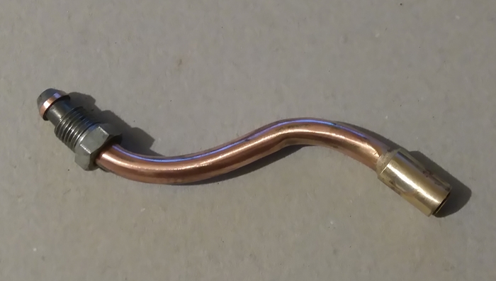 The oil return pipe was the next job. The oil return pipe to the tank was missing but I managed to get a replacement from AMC Classic Spares. As seems to be par for the course with this project, it wasn't quite right. The replacement was 3/8" diameter and all the other pipes were 1/2" diameter. That meant that I had to nip over to my sister's place to use my brother-in-law's lathe to turn up a brass sleeve. That was then silver soldered over the smaller pipe to bring it up to the correct 1/2" diameter so that the 1/2" bore rubber hose would fit. No big deal, really, but it all takes time. One little spark of good news... I tentatively offered up the primary chain case with the new, improved rubber seal and it looks very much like it might actually fit. The clamping screw for the aluminium cover band will need to be changed but hey ho... Did I really expect anything less?
 Saturday, 25th November, 2017. Another cold but bright and sunny morning but rain was forecast for later so instead of attending the monthly coffee morning at the Two Wheel Centre, I set to work on the primary dive. The inner chain case half was already in place so first thing was to fit the dynamo. It was left loose as I would need to adjust it once the drive chain was in position. The new drive chain was 'endless' so it had to be fitted to the drive sprocket and the dynamo sprocket at the same time. That was no problem. The dynamo sprocket retaining nut was tightened, the crankshaft shock absorber cam and spring were fitted and the retaining nut for that fully tightened as well. The chain alignment was set by moving the dynamo in it's clamp and as the armature is not concentric with the body, the chain tension was set by rotating the dynamo. With all that sorted, the dynamo clamp was finally tightened. And so to the primary drive itself. It was a bit of mystery as to whether it would all line up correctly. As you may remember, I've fitted an AMC gearbox from a 500cc 1960 AJS M18S. That machine would have had an alternator fitted where the crankshaft shock absorber mechanism is fitted on my engine and would also have had a cast aluminium chain case. I have no real idea if the primary drive sprockets will line up. Time to find out...
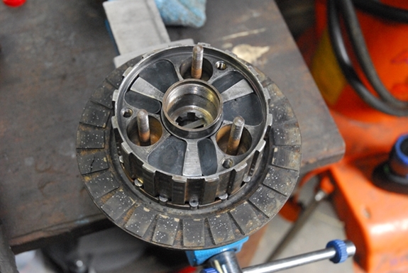
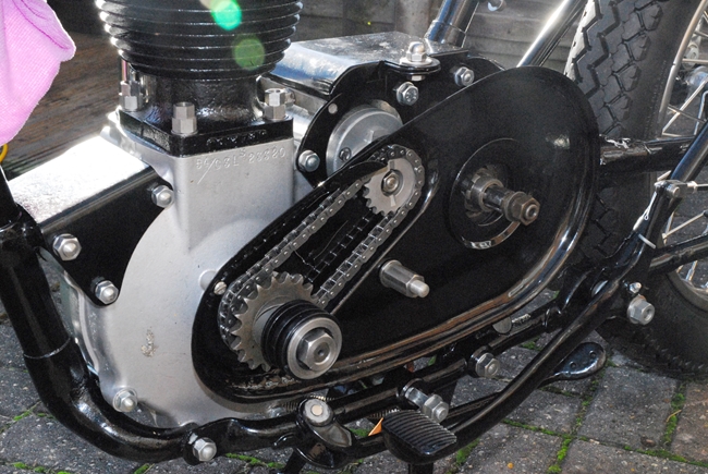
The reason for fitting the AMC gearbox in the first place was because I didn't have a clutch assembly for the Burman gearbox that was fitted originally. I did, however, have a complete AMC clutch so I know that it will fit the gearbox. The clutch hub was slipped onto the gearbox mainshaft and the retaining nut and 'Nord-Lock' washer done up finger tight... I may have to have it off again!! With that in place, the clutch basket was fitted. 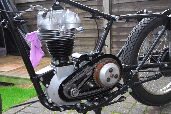 I checked the sprocket alignment with a steel 'straight edge' and yippee... the sprockets line up perfectly. That makes me a very happy bunny!! The retaining nut was fully tightened, the remaining plates were oiled and fitted into the clutch, followed by the pressure plate and its associated springs and retaining nuts. For some reason, the clutch pushrod that came with the bike had been cut in half and a steel ball fitted between the two halves. That wasn't correct so a new pushrod has been fitted. Time to fit the clutch cable and see if it all works. Unlike the cables I fitted yesterday, the new clutch cable fitted perfectly. What's more... once it had all been correctly adjusted, the whole clutch assembly works as it should. That is a big relief. That just left the chain to fit. The AMC clutch has two more teeth on it than the Burman item it replaces so I bought a new chain that was a little longer than normal. The gearbox was adjusted to its forward most position and the chain offered up. I had to shorten it by a couple of links but that done and the chain fitted, the gearbox was re-adjusted to set the correct tension. That was it for today.... apart from pouring the requisite amount of straight SAE50 mineral oil into the gearbox. Incidentally, that isn't rust on the clutch drum. For some reason the clutch drum has been copper plated. I don't know if that was standard for all AMC clutches but it's quite nice!!
 Thursday, 30th November, 2017. Another bright but cold day so time to do a little more. I've got all the tinware back from Ernie and today, I thought I'd like to get some of it installed. The front mudguard was the first item to go on. That's a simple job, but the front wheel has to be dropped out first. Once the guard was in position, the front brake anchor stay was offered up on the near side. The screws into the fork sliders were done up finger tight and the front stand was attached. With that in position and locating the mudguard, the screws into the fork sliders were fully tightened. The wheel was put back in; the front brake anchor bolted to the brake plate and that was that. It just required the front brake cable installing and that job was finished. Like the clutch cable, the front brake cable fitted perfectly for which I was very grateful.
 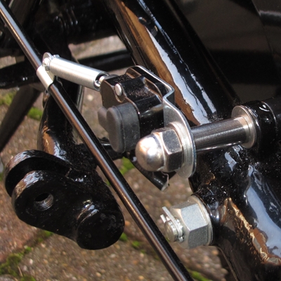 The rear mudguard was the next item on the agenda. I could put it on with the rear wheel in situ but it's much easier to get to the fixings with the wheel out of the way so out it came. It had been 'test fitted' before being painted so I have all the brackets, fixings and spacers to hand. It all went back with remarkably little drama. The new rear chain guard that I bought from AMC Classic Spares has been powder coated gloss black. That was the next thing on the list for today. I'd already fitted it before it was powder coated so that too went on without problems. I'm utilising the reward chain guard fixing to mount the rear brake light switch so the original bolt has been swapped for a longer piece of 5/16" U.N.F. stainless steel threaded rod. I've made up a spacer from a short length of 8mm I.D. stainless steel tube and secured it all with a stainless dome nut. I think it looks OK... Particularly as I've been unable to find out just how the rear brake light switch was mounted on the original bike. I seems that the 1954 model was a 'one-off' year and different from the bikes that preceded it and those that came after. With all that done, the rear wheel was put back. It will probably have to come out again when I start on the wiring harness but for now, it's easier to keep it in.
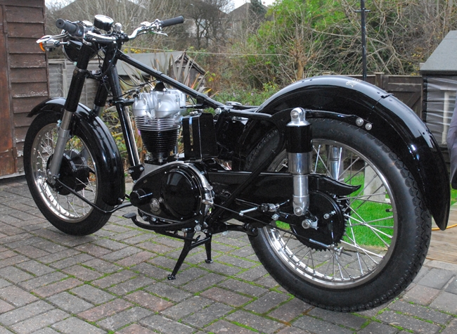 Monday, 4th December, 2017. Time to bolt on a few more bits. The primary chain case outer cover was first. I'd sourced a length of the improved "T" section rubber sealing strip and a new aluminium clamping band from AMOC spares so hopefully it will seal even if the joint faces aren't perfectly flat. The clamping screw that was supplied with the aluminium band was no longer long enough as the new rubber seal is thicker than the old one so I used a length of M5 stainless studding and some long stainless nuts. I tapped the clamping band with a rubber mallet as I tightened the nuts. It re-shaped the band slightly to fit the case better. That worked and the ends pulled together reasonably well. The clutch dome was fitted with new stainless screws and a new cork gasket. The small stainless inspection cover is also new. The battery carrier and oil tank were next on the list. They use the same two attachment points on the frame and need to be fitted at the same time. They both have a (different) third fixing. The oil tank bolts to the rear mudguard which I'll sort out when I next have the rear wheel out and the battery carrier needs a bracket to secure the bottom to the back of the primary chain case.
 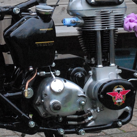 There was one among the bits I bought from Malcolm but it's just too rusty and corroded to use. If I cleaned all the rust off, there'd be nothing left but it does fit and will serve as a pattern. I've got some 3mm thick mild steel strip that I'll make a new one from.
That just leaves the oil pipes to do today. The two short copper pipes at the engine end are a real pain in the backside. They are awkward to get at and extremely easy to cross-thread if you're not very careful. In the end, I removed the nut from the adjacent engine mounting stud. That gave me just enough room to get the top pipe installed. I had to replace the full nut with a thin lock-nut as there was not enough room for the full one with the pipe in situ. The lower pipe was a bit easier but it still took me a good half an hour to fit them both to my satisfaction. I was going to fit the braid covered rubber pipes but decided to leave that for now. The rubber pipes run under the gearbox and I'm going to give them a bit more protection with some heat shrink sleeving over the braid but I don't have any of the correct size. I've ordered some but it won't arrive until later in the week.
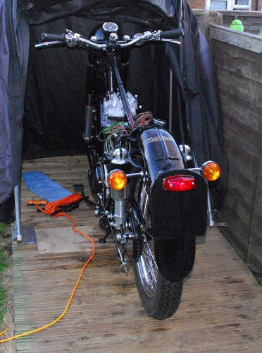 Friday, 8th December, 2017. Whilst storm 'Caroline' has been causing havoc with high winds and snow in the northern reaches of the Kingdom (Queendom?), in my part of the country it's been fine and sunny, albeit with a cold northerly wind. Not too uncomfortable so I managed to do some more work on Alice. Completing the oil system was first priority. The tank is now connected to the engine with braid covered nitrile rubber hoses. A new fine mesh filter was installed in the feed hose. Next on the list was the two 'third fixings' for the oil tank and battery carrier. I'd fabricated and painted a new 'stay' for the bottom of the battery carrier so that was just a case of bolting it on. With the rear wheel removed, bolting the oil tank to the rear mudguard was also a simple task. With those jobs completed, it's time to start looking at the wiring. As is my usual practice, I'll start at the rear end and work my way forward, creating the wiring harness as I go. That means that the rear number plate, complete with the rear light had to be sorted and fitted. That was another relatively easy task. Bearing in mind that the rear half of the mudguard is hinged to allow the rear wheel to be removed, the wiring to the tail light and stop lamp has to be 'broken' at the joint so I've used a 3 pin 'TYCO AMP' waterproof plug and socket (rear light, stop light and ground return). That will make disconnecting the rear light easy if I need to removed the rear wheel for any reason. The rear indicators are fitted to the fixed part of the mudguard so they don't need to be disconnected. It took a bit longer to do than it did to write this but that's the back end of the bike completed. I've not actually tested the wiring yet but I have complete confidence that it will work perfectly.
Saturday, 9th December, 2017. Another bright, sunny but very cold morning. First thing was to check the wiring I did yesterday. With a new 6v AGM battery to hand, the various circuits were connected up. Happy to say that everything worked as it should. The only other thing I did this morning was to run wires down to the brake light switch. It was a bit of a struggle convincing two wires that they really did fit into some 4mm PVC sleeving but I prevailed in the end.
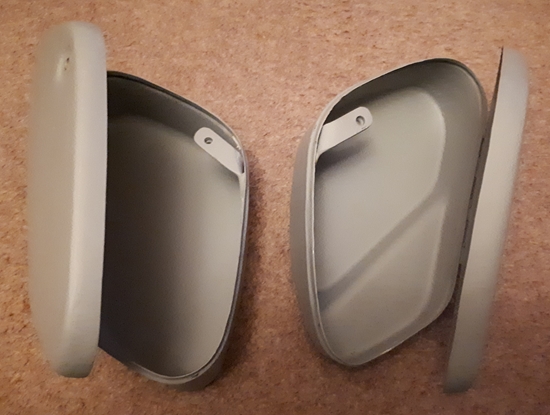 Monday, 18th December, 2017. The two new tool boxes arrived from India a few days ago. Today I had a tentative look at how they would fit. First impressions are that while the boxes aren't perfect, they are close enough to be functional and look the part, particularly as they will be on opposite sides of the bike. I'm sure when they've had the 'Ernie' treatment, they will be perfect. Hopefully I'll be able to get the fixing holes drilled in the correct places later this week and then take them over to Ernie's after Christmas
I've also carried on with the electrics. The battery has been installed as have the solid state dynamo regulator and fuse box. The wiring to the rear of the bike is now complete and I'll start working forward soon but before I can get much further, I'll need to find a horn and fabricate a bracket to secure the ignition coil under the front of the frame top tube where it will be hidden by the fuel tank when that's in place. I have an idea for that...
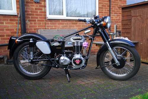 Saturday, 30th December, 2017. The year is almost over and it's been almost exactly 10 months since I started this project. I won't say that it's been an easy project... it's had its 'ups' and 'downs' but on the whole, I'm satisfied with the way things have gone. In the great scheme of things there's not a lot left to do. The ignition coil has been mounted and the tool boxes have been mounted temporarily to check that they are fit for purpose. They aren't the best quality but they won't look bad when they are finished. They are now ready for the final paint job of the project and I'll let Ernie work his magic on them in the new year. That only leaves the wiring to complete and an exhaust system (yet to be sourced) fitted.
Thursday, 22nd February, 2018. I have to say that things have progressed with exceeding slowness over the winter but there has actually been some... progress, that is. I now have the tool 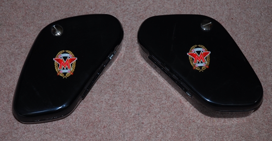 boxes back and Ernie has worked his usual magic as they look superb. The photo doesn't do them justice. I'm not sure when they'll get fitted as there is more snow forecast for the coming week or so which precludes any work being done outside.
Friday, 23nd March, 2018. I've finally managed to do a little more to the bike today. This last month or so has been a bit frenetic. What with the blizzard conditions that the 'Beast from the East' unleashed upon us, a weeks fishing in Norfolk where I managed to haul out a new personal best pike of 24lb 7ozs and a couple of sessions fixing Tractor Dave's 'Little Grey Fergie'... again, I haven't had a lot of time to do much to 'Alice'. However, I digress... The tool boxes that Ernie has painted are now firmly attached to the bike and set the whole thing off nicely. Those of you that have been keeping up, 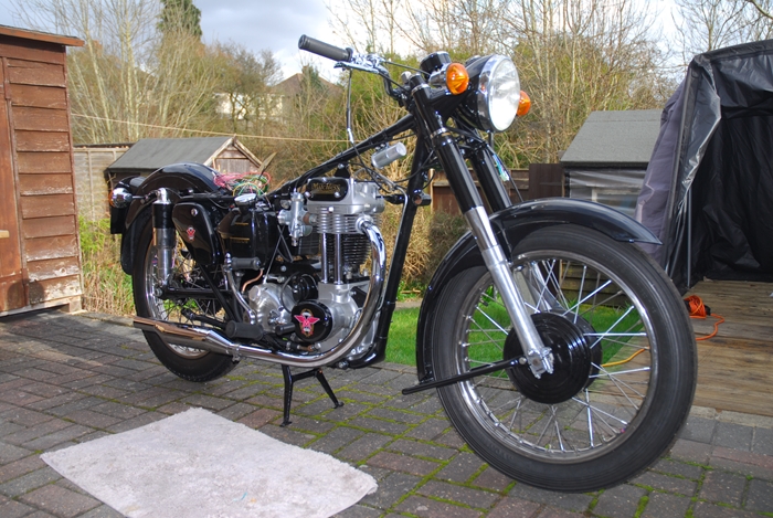 will no doubt remember that I chose to install a later, 1960(ish) AMC gearbox rather than the original '54 Burman box. There were two main reasons for that decision. (A) - it was in much better condition and is, by general consensus, a better gearbox and (B) - it was fitted to other makes of bike, most notably Norton and 'bits' are easier to come by. As I said right at the beginning of this saga, there were a number of significant parts missing that would have to be sourced from somewhere. Fitting the AMC gearbox made obtaining two of them easier. The folding kickstart crank is from a Norton 'Atlas' and the gear change lever is from a Norton 'Commando'. I won't tell anyone if you don't!. The foot pegs have been bolted on and it obvious that the right hand one is just a little 'bent'. That will have to come off again at sometime and be straightened (or be replaced as I think there are some spare ones in the garage somewhere). However, in the short term, I'll use it as it is.
The exhaust system gave me some cause for thought. There are various suppliers of 'pattern' parts, 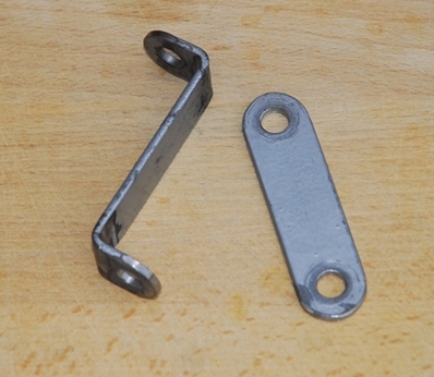 all claiming to have the best product. After some internet searching and getting advice from other owners, I bought a pipe and silencer from 'Feked'. It arrived quickly and looks good. The pipe is heavy gauge steel and the welds on the silencer have been linished off and are nice and smooth. There was only one slight 'niggle'. There are mounting studs welded to both the pipe and the silencer. They should be 5/16" B.S.Cy thread. They aren't. The one on the silencer is 5/16" U.N.F. and the one on the pipe in metric M8. Other than that, it fits nicely but I had to fabricate a couple of brackets from some 1/8" thick, 3/4" wide mild steel strip as nobody seems to be manufacturing replicas of these parts (maybe another job for John Thomas at JtClassic Stainless?). The simple one is for attaching the silencer and the 'Z' shaped one secures the exhaust pipe to the mounting stud at the front of the engine. They will be fettled and painted in the fullness of time. The last thing I did today was mount the new carburettor and control cables. In the great scheme of things, there's not an awful lot left to do. The wiring has to be completed but I'm waiting on a cable delivery before I can carry on with that.
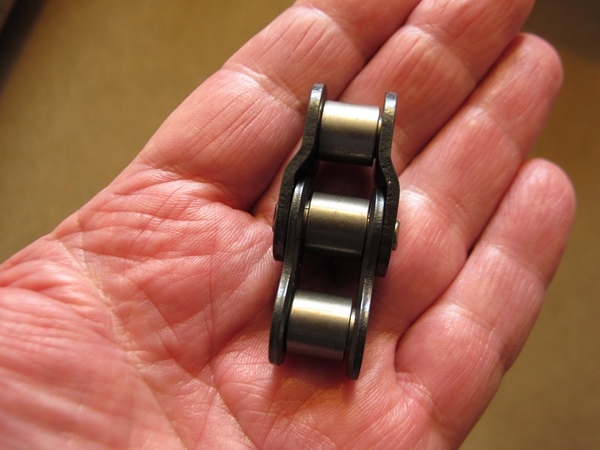 Saturday, 7th April, 2018. I've done a little more over the last two days. The final drive chain has been fitted. If you remember, I had to change the gearbox sprocket size from 16 to 18 teeth to compensate for the increased number of teeth on the AMC clutch basket. That meant that with the limited movement available at the rear wheel, I had to create a 'odd' number of links in the chain by fitting a 'cranked' link (or a "link and a half" as they are sometimes known). I wouldn't use one normally but it won't cause a problem on this bike with it's low power output! With the chain fitted and the rear wheel fully tightened, I could fit the speedometer cable and lock the drive gearbox in position. Two more jobs completed.
The silencer mounting bracket that I made earlier wasn't quite right. It needed to be a little longer to ensure that the pipe fitted fully into the cylinder head. I've made a new one from a piece of 1" wide x 3mm thick stainless steel. That allowed the pipe to fit correctly and the system has now been finally installed with a little exhaust pipe paste around the joint and a finned collar around the pipe at the cylinder head. Another task completed and time to carry on with the wiring. Hopefully, if the weather is kind to me, it shouldn't take too long.
Sunday, 15th April, 2017. A good day... I've completed the wiring and it all checks out... now. I'd left the battery connected while I was doing the wiring so that I could check each circuit as it was completed. It all worked up until I tried out the indicators... nothing! I checked the circuit and scratched my head while I tried to suss out what was wrong. Then it clicked... I'd confused a brown wire with a white trace and a white wire with a brown trace. I'd managed to get them swapped over. A silly mistake on my part. It meant undoing half of the harness I'd so carefully wrapped but it was easily rectified with no damage done. So... it now all works; I have lights, indicators, a horn and I've even got a spark when I kick it over. At the moment, I have an LED stop/tail 'bulb' and an LED pilot 'bulb'. Tomorrow, I'll order an LED headlight 'bulb' and 4 LED indicator 'bulbs'. That will significantly reduce the current drain on the small 6v battery and give the switches and dynamo an easier time of it. I've used an electronic flasher unit so changing from incandescent bulbs at 21 watts each to LED 'bulbs' at 3 watts each shouldn't affect the flash rate.
Monday, 16th April, 2018. I thought things were going too well. Today was NOT a good as I've hit a significant 'snag'! The new dual set that I bought from AMOC Spares doesn't fit too well. In fact, it doesn't really fit at all. Having got the tank on and sorted out the fuel pipes, I offered up the seat to it's mounting points. With the front mounting point engaged, the rear mounting holes are a mile off. Ok... I could drill a couple of new holes in the frame but I didn't really want to do that and anyway, that's not the only problem with it. The sides are too deep and foul the tool boxes, which means it's sitting too high at the front and looks bad. It turns out that these replica seats are made by "Wassell" and if you've been around old Brit Iron for any length of time, you'll know that their reputation for quality is non-existent. I'm not going to ruin the bike by trying to make it fit. I've done what I should have done in the first place. I 'phoned R. K. Leighton in Birmingham. They supplied a new seat for the Bonneville and re-upholstered the original seat for the Tiger 90. They are going to make me a new seat, guaranteed to fit. Only problem is that they are made to order and it will be two or three weeks before I get it. Ho hum... Still, it did give me a chance to take the Bonneville out for it's first run of the year this afternoon.
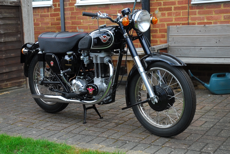 Thursday, 10th May, 2018. The new seat arrived from Leighton's yesterday and it looked the business. Today, the sun was shining so it was time to see if their claim that it would fit perfectly was valid... It was. The holes lined up as they should and it was fitted without any drama. It was taken off again because the tank has to be fitted first and before I could do that, there were a couple of things I needed to do. The battery had been on the bike for some weeks and I'd been playing about with the lights and indicators whilst doing the wiring so that was connected up to the charger for a quick boost. As this bike has coil ignition, not the original magneto, it requires a battery so I wanted to make sure it was fully charged. Also, before the tank went back, I wanted to pour an egg cupful of oil into the the top of the engine via the tappet cover. That would drain down the pushrod tubes, lubricate the cams and ensure that there was some oil in the crankcase to prime the return oil pump when (if?) the engine was started. That done, the tank was fitted, the fuel lines connected up and the seat put back on. The gearbox had been filled with oil a while back so now the oil tank was filled with Castrol 'Grand Prix' straight SAE50 mineral oil. The primary chain case was also filled up to the requisite "1/8" below the inspection cap". That's it... She really does look like a proper motorcycle now and the boxes of bits I started with have finally become "Alice". Tomorrow, all being well, I'll put some petrol in the tanks and we'll see if she actually wants to run!
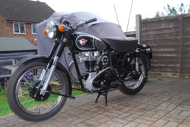 Saturday, 12th May, 2018. Got up bright and early yesterday morning. I went over the bike again and checked that all was well and I hadn't forgotten anything. At this point, I thought I would record what was to happen next for posterity so I set the 'GoPro' up on a tripod and set it recording. I emptied a 5 litre can of premium petrol dosed with Castrol 'Valvemaster' into the tank and 'tickled' the carburettor. A couple of prods on the kick start to suck some fuel into the engine and I switched on the ignition. A hefty kick on the kick start and the engine fired... just the once. That was promising... A few more kicks, another 'tickle' and she fired up and ran. Oh, yes... she was running perfectly. I took the cap off the oil tank to check that the oil was being returned from the engine. There was no sign of it but I wasn't expecting it to return immediately. It takes time for the oil to circulate. A tense few minutes passed and the first trickle of oil appeared. I was a very happy bunny! I let her run for a few minutes then switched her off. The video is on my "YouTube" channel and can bee seen HERE if you're remotely interested.
Not such an early start this morning. There were a couple of things I needed to do on Alice. Yesterday, when I started her, I noticed that the kickstart lever wasn't in quite the right position on the shaft so I moved it round a couple of splines. The second thing was to refill the swinging arm reservoir with the correct grade of oil (Castrol D140) as the SAE50 oil I filled it with some months ago had mostly drained out. 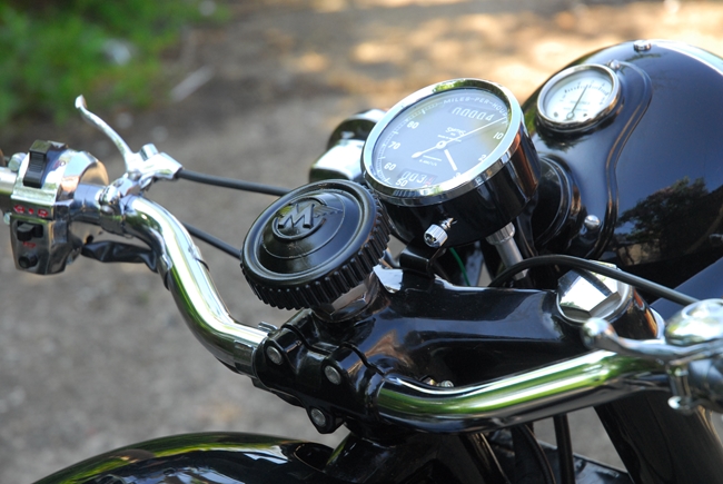 That done, I started her up again. I knew I shouldn't have done but I had to take her for a short run around the block. I needed to know that the gearbox was OK and that there were no other problems. I'm happy to say that firstly, the gearbox works perfectly. Secondly, the overall gearing ratio that I'd chosen seemed to be OK, too. She pulled away from a standing start easily so the ratio wasn't too high. Everything else seems fine. The job's a good 'un...
Saturday, 19th May, 2018. I'd noticed a couple of things during my all too brief ride around the block. First and most obvious was that I couldn't hear the indicator warning 'buzzer' with the engine running and me wearing a crash helmet, so there was the potential to 'forget to turn them off' after I'd made a turn. I would need a visual warning lamp. Places to install a warning lamp are a bit limited but having had a look and a bit of a think, I'll mount one in a bracket that will be held under the left hand fork cap nut. 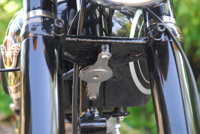 If the bracket is polished stainless to match the nut, I don't think it will look too out of place. I've found a place on t'web that will laser cut custom 'one off' items so I'll send them a drawing and see what they can do.
The second thing I noticed was that the pot holes and the general crappy road surface that we seem blighted with was causing the steering to shake a little so I've installed the friction steering damper that was an 'optional extra' when the bike was made. There was one amongst the bits that I bought from Malcolm so I dug it out, cleaned it up and fitted it this morning. I had to buy a new lock nut and stem cap to replace the dome nut that was normally fitted. The bits were available from AMOC Spares and they arrived a couple of days ago. I've sent off all the documents to the DVLA so I'm hoping that I will get a registration number for her sometime in the next week or so. Then I'll be able to take her out and see if the damper has made any improvement.
Thursday, 24th May, 2018. I've heard back from Lasermaster Ltd, the company I contacted about getting a mounting plate for the indicator warning lamp laser cut from stainless steel. They'd received my drawing and have agreed to make a couple for me. I only need one right now but I may put indicators on the AJS in due course and I will use the second one for that if works OK on the Matchless. They are quoting 5 to 7 working days so I shouldn't have to wait too long to try it out. Happy days.
Wednesday, 30th May, 2018. A week ago I collected together all the documentation required for an age related registration number and sent it off to those very nice people at the DVLA. Yesterday the postman brought me a letter from Swansea. Yippee.... A new registration.... or not!!! It seems that those not very nice people at the DVLA don't trust me. They are requiring independent verification that the machine is as I've described it. They want an inspection by the SGS (their vehicle inspection bods). I phoned them immediately to sort it out. Today they phoned me back... an inspector is coming a week on Monday to take photographs of the bike, the frame number and the engine number. Those nasty people at the DVLA can then compare them with the photos I sent them a week ago. Ho hum....
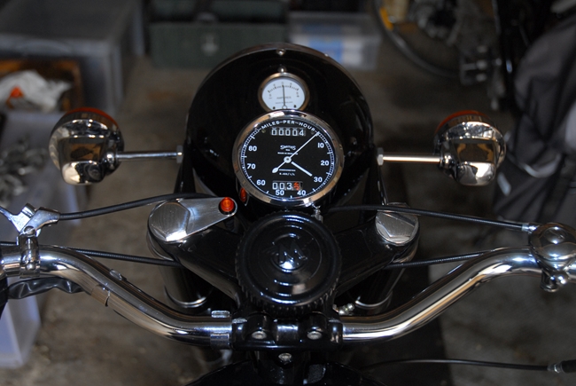 Monday, 4th June, 2018. Jeez... It's June already. Where the hell has this year gone?? The two plates I ordered from Lasermaster Ltd arrive last week. They are perfect... exactly as I'd drawn them. I'd not asked for any special finish but the faces had been 'brush finished' anyway. The edges were just raw 'laser cut' so I spent a few minutes smoothing them with the Dremel and then polishing on the buffing wheel. I fitted one of them under the left hand fork cap-nut and installed the LED indicator lamp. It's not quite as bright as I'd hoped but it's right 'in my face' so I shouldn't have any problem seeing that the indicators are on. Something that has been on my mind is the position of the exhaust valve lifter on the left hand side of the handlebars. Because I've got the switch cluster for the indicators etc. on that side, I've had to fit the lifter lever a little in-board and on top. It's not ideal. However, I find I can kick start the bike easily without having to use the lifter so I may remove it later on. It's a brand new bore and piston that hasn't been 'run-in' yet and I may find that I need lifter if the compression is better once the new rings have bedded in. Time will tell.
Monday, 11th June, 2018. The Man From Delmonte... he say "Yes"... Well, not quite. It was the man from SGS and he said "Lovely, so much better than the piles of junk we're normally asked to look at!". Alice was inspected for the DVLA this morning and the inspector was impressed. He took all the details and numerous photographs. He will pass them to the DVLA later today so they will be there in the morning. He recons it takes about 5 days to process after they get the information so hopefully, I'll hear from them early next week.
Tuesday, 19th June, 2018. When the inspector came last week, he advised me to 'phone the DVLA if I hadn't heard from them after 5 or 6 days so today I did just that. After a few minutes messing about to find the right number and then more time going from one 'choice' to another, I eventually got to talk to a bloke in Old South Wales. I gave him the reference number and asked what the situation was. After giving him my name and address, date of birth, make and model of the vehicle, my inside leg measurement, religious and sexual orientation he gave me the good news!! My application had been dealt with and the documentation was posted to me last Friday. Hopefully I'll get it tomorrow's post. He could, however, give me the registration number that had been allocated... "569 XVB". I've ordered a new number plate and as soon as I get the V5C document, I'll make sure every thing is OK and get the insurance sorted out properly. It's been quite a journey!!
Monday, 25th June, 2018. The V5C document turned up on my doormat last Wednesday... and it wasn't correct. Why doesn't that surprise me? Despite me filling in the V55 form in block capitals, sending them a very clear photograph and the SGS inspector also sending them a photograph, they had managed to get the engine number wrong. The number clearly starts "53G3LS.....", they had managed to put "5393LS....." on the V5C. Another phone call to the DVLA and it will be sorted. I just have to correct the document and send it back to them whereupon they will issue a new, correct V5C. Ho hum...
The number plate I ordered has arrived and was fitted this morning. Alice clearly took umbrage at having a number plate screwed to her backside and the sulky cow refused to start. Plenty of fuel but no spark. The problem proved to be the contact breakers. For some reason they had decided not to conduct electricity even when they were closed. I suspect it was because they were "new, old stock" when I bought them and had oxidised over the years whilst laying on someone's shelf. A quick polish with fine emery paper sorted that out. Time to take her out for her first (legal) road test. It didn't go well, I have to say. A few minutes into the trip, there was a loud 'graunching' noise and a serious rattle from the primary chain case. As I pulled into the side of the road, I realised that I had no clutch. The cable was complete slack which meant I couldn't change gear or select neutral. Something, as they say, was amiss. An hour later she was back in the garage having been pushed home. All very embarrassing.
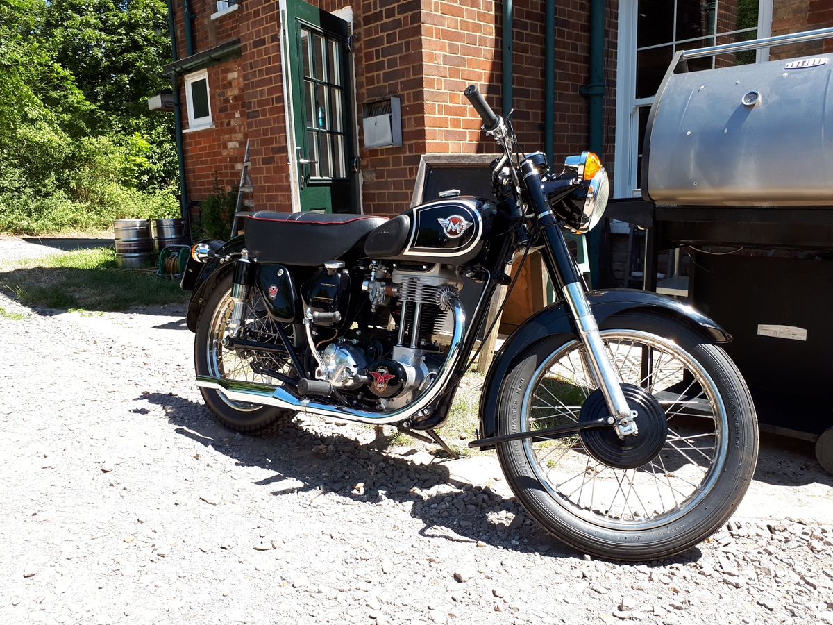
Tuesday, 26th June, 2018. This morning saw me bringing the bike up from the garage. Time to find out what had happened so I unscrewed the eight screws that hold the domed clutch cover onto the outer half of the primary chain case. Aha... The locknut on the clutch pushrod adjusting screw had come undone (or maybe I hadn't fully tightened it as I've never had that happen before). This had allowed the screw to unwind out of the pressure plate and drop between the pressure plate and the cover. Fortunately, there was no damage other than a little paint scraped off the inside of the cover. It was all put back and re-adjusted, this time ensuring that the lock nut was fully tightened. Time for another test ride. This time, all went smoothly. After a couple of turns 'around the block', I headed out to The Strathmore Arms at St Paul's Walden as Alice had informed me that she was feeling thirsty. A swift pint and then over to The Two Wheel Centre to introduce her to Nick, Sophie and Les (not to mention getting a cup of tea!). Then it was back home. Everything seemed OK with the possible exception of the clutch cable. It really isn't as smooth as I'd like. It was new cable, purchased from AMOC Spares but I think I'll swap it out for one of Venhill's custom 'Featherlight' jobs which means taking this one off and sending it to them as a pattern. Not to worry, I've still got a couple of Triumphs I can ride for now. One last thing... The indicators... The switch is a bit 'micky mouse' and I'll look for a better one but it is working for the moment. With the LED bulbs, the light is directed forward rather than all around as is the case with a normal incandescent bulb and I can't see if the front indicators are actually working. The warning LED that I fitted recently is not very bright and in sunlight, I can't see that either. The warning buzzer can't be heard over the engine so at the moment, I have to be aware that I can, inadvertently, forget to turn them off. Until I can come up with something better, I've swapped the LED bulbs back to the old 6v 21w bulbs. When they are on, they are drawing around 7 amps and that is just about the maximum output of the short E3N dynamo. Consequently I get a large discharge deflection on the ammeter. That is probably the best indication I've got at the moment and as a bonus, if the weather is dull enough, I can actually see if the front indicators are flashing.
Monday, 9th July, 2018.... Update. Alice and I have covered approximately 280 miles together now and it has been pretty much trouble free. In fact, she runs like a dream and hasn't missed a beat. As the bore and piston are new, I've been keeping the revs down and cruising around 40 m.p.h. with occasional short bursts up to 50. There is no sign of any tightness and the rings seem to be bedding in nicely. The compression has got better and she's burning very little oil. The clutch has behaved itself and I've had no more trouble with that. There have, however, been a couple of 'niggles'. The high tech electronic flasher relay has proved un-reliable. It flashes at a rate to suit itself... anything from extremely rapid to very slow. That has now been replaced with a more reliable, old style, bi-metallic strip relay. The bulbs are 18w incandescent lamps and the indicators now flash at the correct rate... reliably. The only other problem I've had is with the chronometric speedometer. At 66 miles recorded, both the main odometer and the trip odometer stopped recording although the instrument was still indicating the correct road speed. It had been serviced and re-calibrated at Chronometric Instrument Services Ltd and was still under warranty so I sent it back. They repaired it free of charge and sent it back. It worked perfectly for another 170 miles before packing up again in exactly the same manner. So back it went to CIS and I asked them to 'phone me when they'd had a look at it. They phoned me this morning. Apparently, a small brass lever in the mechanism had broken. The very nice gentleman I spoke to said that in 40 years of servicing these speedometers he'd never, ever seen one broken before. He is going to install a complete new mechanism, free of charge. Good service indeed... !! I'm expecting it back tomorrow and we'll see how long it lasts.
So ends part 2...
The saga continues... See "Part 3" by clicking HERE.
Link to G3 parts as bought from Malcolm.
Link to Index and Home Page.
Link to Matchless G3/LS - Part 1.
Link to AJS M18S page.
Link to Triumph T120R Bonneville page.
Link to Triumph Tiger 90 page.
Link to Matchless G80CS page.
Link to Honda VFR750 page.
Link to Norton 650SS page.
Last updated 24/10/2021